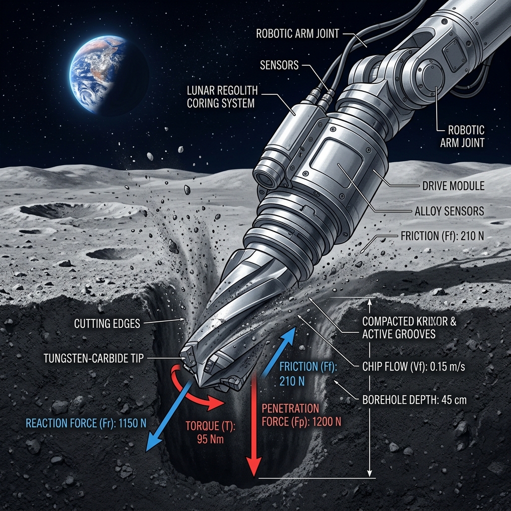
Lunar Regolith Drilling Mechanics & Space Exploration
1. Subsurface Lunar Exploration & Geotechnical Challenges
Subsurface exploration of the Moon represents the next frontier in planetary science, in-situ resource utilization (ISRU), and the establishment of permanent human habitats. While orbital remote sensing has mapped the lunar surface topography and mineralogical distribution with high resolution, it remains blind to the geotechnical, thermal, and chemical properties of the deep subsurface. Accessing these subterranean volumes requires robust excavation and drilling systems capable of penetrating highly compacted, abrasive regolith and consolidated rock layers.
The primary target of extraterrestrial drilling operations is the lunar regolith. Formed through billions of years of continuous micrometeorite bombardment, solar wind implantation, and extreme thermal cycling, the regolith is a poorly sorted, highly angular silty sand. Unlike terrestrial soils, which are weathered by wind, water, and biological activity, lunar regolith particles retain sharp, jagged profiles with high aspect ratios. This unique particle morphology results in mechanical behaviors—such as extreme shear strength and dilatancy—that pose severe challenges for robotic drilling assemblies.
For long-term lunar settlement, drilling is critical for three primary reasons. First, the extraction of volatiles (specifically water ice trapped in the permanently shadowed regions (PSRs) at the poles) is essential for life support consumables and rocket propellant production. Second, scientific coring is necessary to analyze the stratigraphy of the regolith, which preserves a historical record of the solar system and galactic cosmic rays. Third, drilling is required to install geotechnical anchors, structural supports, and thermal loops for lunar bases, as well as to excavate regolith to construct protective radiation shields.
2. Geotechnical and Physical Properties of Lunar Regolith
Designing an efficient lunar drill requires a highly quantitative understanding of the regolith's physical characteristics. Soil mechanics parameters vary dramatically as a function of depth, reflecting the transition from loose, fluff-like surface material to a state of extreme consolidation.
2.1 Depth-Dependent Density Profile
Analysis of core samples returned during the Apollo 15, 16, and 17 missions, as well as the Soviet Luna landers, revealed that the bulk density of lunar regolith increases rapidly within the first 30 cm and then asymptotically approaches a high steady-state value at depth. This compaction is primarily driven by the acoustic shaking and mechanical pressure of historical meteorite impacts. Carrier et al. (1991) formulated an empirical model that represents the bulk density \(\rho\) as a function of depth \(z\) (in centimeters):
where the typical parameters derived from historical core analysis are \(\rho_{\infty} = 1.92 \text{ g/cm}^3\), \(a = 12.2 \text{ cm}\), and \(b = 15.8 \text{ cm}\). At the immediate surface (\(z = 0\)), the bulk density is approximately \(1.48 \text{ g/cm}^3\). At a depth of 30 cm, the density reaches \(1.78 \text{ g/cm}^3\), and at a depth of 100 cm, it exceeds \(1.86 \text{ g/cm}^3\), representing an extremely dense, compact packing of angular grains.
2.2 Cohesion and Shear Strength (Mohr-Coulomb Model)
The shear strength of lunar regolith is governed by the Mohr-Coulomb failure criterion, which relates the shear stress \(\tau_f\) at failure to the normal stress \(\sigma_n\) on the failure plane:
where \(c\) is the cohesion of the material, and \(\phi\) is the internal friction angle. For lunar regolith, both parameters are depth-dependent. Near the surface, the cohesion is very low (\(c \approx 0.1 \text{ to } 1.0 \text{ kPa}\)) because the particles are loosely bound under weak gravity. However, at depths below 30 cm, the cohesion increases to between \(3.0 \text{ kPa}\) and \(10.0 \text{ kPa}\), and can exceed \(20.0 \text{ kPa}\) at depths of several meters due to interlocking of highly angular particles and cold-welding in the ultra-high vacuum environment.
The internal friction angle \(\phi\) is exceptionally high compared to terrestrial soils of similar grain size. Due to the complete absence of liquid water and atmosphere, the particles are clean and have sharp, unweathered facets. Friction angles typically range from \(\phi \approx 35^\circ\) to \(48^\circ\), increasing with relative density. When compacted, the regolith exhibits strong dilatant behavior, meaning it must expand in volume to shear, which drastically increases the apparent resistance to penetration.
2.3 Relative Density and Porosity
The relative density \(D_r\) is a measure of the packing state of the soil relative to its loosest and densest possible states:
where \(e\) is the void ratio, \(e_{max}\) is the maximum void ratio (loosest state), and \(e_{min}\) is the minimum void ratio (densest state). In-situ measurements indicate that the relative density increases from around \(60\%\) at the surface to over \(90\%\) below 30 cm, and reaches nearly \(99\%\) at 1 meter. This extreme compaction means that the soil has virtually zero remaining pore space, causing the regolith to act as a highly consolidated rock-like matrix under the action of a drill.
3. Mechanics of Cutter-Regolith Interaction: Cutting Force Derivation
To model the forces acting on a drilling bit, we must analyze the interaction between an individual cutting tooth (or cutter blade) and the regolith matrix. In geotechnical cutting mechanics, this is typically represented by a two-dimensional failure wedge model, which adapts classical metal cutting principles (such as Merchant's Circle) to cohesive-frictional geomaterials.
Consider a flat cutter of width \(w\) executing a depth of cut \(d_0\) at a rake angle \(\alpha\) (where a negative rake angle represents a face tilted forward, resisting penetration but strengthening the tool). As the cutter moves horizontally at a cutting speed \(v\), a passive shear plane develops at a failure angle \(\beta\) with respect to the horizontal cutting direction.
Figure 1: Force vectors, failure plane geometry, and chip flow dynamics at the cutter-regolith interface.
3.2 Force Equilibrium and Cutting Stress Equations
To derive the cutting force \(F_c\) and thrust force \(F_t\) required by a single cutter, we write the static equilibrium equations of the soil wedge. The forces acting on the wedge are:
- The resultant cutting force \(R\) exerted by the cutter blade on the wedge. \(R\) is inclined at the blade-soil friction angle \(\delta\) relative to the normal to the cutter face.
- The shear force \(S\) resisting motion along the failure plane: \(S = c \cdot A_s + N_s \tan \phi\), where \(A_s = w \cdot d_0 / \sin \beta\) is the shear plane area, and \(N_s\) is the normal force acting on the failure plane.
- The weight \(W_g\) of the soil wedge: \(W_g = \frac{1}{2} \rho g w d_0^2 \cot \beta\). Under lunar gravity (\(g = 1.62 \text{ m/s}^2\)) and small depths of cut, this gravity term is tiny compared to the cohesion and friction terms, and can be safely neglected (as demonstrated in Section 6).
Resolving the forces perpendicular and parallel to the shear plane yields:
Substituting \(N_s\) into the Mohr-Coulomb equation \(S = c \cdot A_s + N_s \tan\phi\) and solving for \(R\) (neglecting \(W_g\) due to its negligible magnitude):
The horizontal cutting force \(F_c\) and vertical thrust force \(F_t\) are the components of the resultant force \(R\) projected along the coordinate axes:
In practice, the failure plane angle \( \beta \) is the angle that minimizes the cutting force \( F_c \). According to classical earth pressure theory, this can be approximated by:
4. Rotary-Percussive Drilling Dynamics
Planetary drilling architectures are constrained by stringent mass and power limits. Standard rotary drilling, which relies on high vertical thrust (Weight on Bit, WOB) to shear rock, is unviable on the Moon. Under low gravity (\(1.62 \text{ m/s}^2\)), a rover lacks the downward force reaction to supply high thrust. To overcome this, space missions utilize rotary-percussive drilling.
Rotary-percussive drills combine continuous rotation with high-frequency axial impacts. The percussion mechanism sends shock waves through the drill string to fracture and pulverize the soil directly beneath the cutter, while the rotation scrapes the fractured material and sweeps it away. This method reduces the required thrust force by up to an order of magnitude.
The Rate of Penetration (ROP) in a rotary-percussive drilling system can be modeled using an energy-balance formulation:
where \(E_p\) is the percussion impact energy (J), \(f_p\) is the percussion frequency (Hz), \(\eta_{trans}\) is the shock wave transfer efficiency, \(A_{bit}\) is the cross-sectional area of the drill bit, \(\sigma_{uc}\) is the unconfined compressive strength of the compacted regolith, \(T\) is the rotary torque, \(\omega\) is the rotation speed, and \(\tau_{shear}\) is the shear strength of the regolith. The percussive term dominates in hard formations, while the rotary term dominates in looser, cohesive soils.
5. Heat Dissipation & Thermal Transport in Vacuum
Figure 2: Heat dissipation mechanisms in vacuum, showing frictional heat trapping at the drill bit and propagation of radiative heat waves.
Drilling in the lunar environment presents an exceptional thermal challenge due to the ultra-high vacuum conditions (\(P < 10^{-10} \text{ Torr}\)). Frictional heat generated at the drill bit cannot dissipate via convective cooling, as there is no surrounding atmosphere or drilling fluid to carry the heat away.
Furthermore, dry lunar regolith has an extremely low thermal conductivity (\(k_s \approx 0.009 \text{ to } 0.015 \text{ W/m}\cdot\text{K}\) under vacuum). Because there are no fluid molecules in the pores, heat transfer between regolith grains occurs solely through tiny contact points and radiation. Consequently, the regolith behaves as a nearly perfect thermal insulator, trapping the generated frictional heat directly at the drill bit interface.
Frictional heat generation rate \(Q_g\) at the bit is given by:
A fraction \(\eta_{heat} \approx 0.8 \text{ to } 0.9\) of this heat enters the steel drill bit. Heat can only escape through two paths:
- Conduction along the drill string: \(Q_{cond} = k_{str} A_{str} \frac{T_{bit} - T_{sink}}{L_{eff}}\), where \(k_{str}\) is the thermal conductivity of the drill tube material, \(A_{str}\) is the tube cross-sectional area, and \(L_{eff}\) is the distance to the drill head (acting as a heat sink).
- Radiation to the environment: \(Q_{rad} = \epsilon \sigma_{SB} A_{rad} (T_{bit}^4 - T_{wall}^4)\), where \(\sigma_{SB} = 5.67 \times 10^{-8} \text{ W/m}^2\text{K}^4\) is the Stefan-Boltzmann constant, \(\epsilon\) is the emissivity of the steel bit surface, \(A_{rad}\) is the radiation surface area, and \(T_{wall}\) is the temperature of the surrounding borehole wall.
The governing energy balance equation for the transient temperature response of the drill bit is:
where \(m_b\) is the mass of the drill bit and \(C_b\) is its specific heat capacity.
6. Worked Numerical Example: Forces and Temperature Rise
Let us perform a complete, step-by-step geotechnical and thermal calculation for a robotic lunar drill operating at a depth of 1 meter.
6.1 Input Parameters
We consider a drill bit with diameter \(D_b = 35 \text{ mm}\) (radius \(r_{bit} = 17.5 \text{ mm}\)) equipped with \(n_c = 2\) symmetrical cutters. The drill parameters are:
6.2 Step-by-Step Execution
Step 1: Check magnitude of wedge gravitational weight
The failure plane angle \(\beta\) is calculated as:
For \(n_c = 2\) cutters, the feed rate per cutter per revolution is:
Step 2: Calculate Cutting Force \(F_c\) and Thrust Force \(F_t\) per cutter
Using the derived equations:
Step 3: Calculate total Torque \(T_{total}\) and total Thrust \(F_{thrust}\) at the bit
The cutters operate at an effective radius of \(r_{eff} = 12 \text{ mm} = 0.012 \text{ m}\).
Step 4: Calculate heat generation rate \(Q_g\) and thermal energy entering the bit
The angular velocity is:
Step 5: Calculate temperature rise \(\Delta T\) after 10 minutes (600 s) in vacuum
The thermal capacity of the bit is:
7. Comparative Analysis of Lunar Drilling Systems
To place these physical calculations in context, we compare historical and upcoming planetary drilling architectures.
8. Engineering Design of Lunar Drills: Auger Geometry & Materials
Figure 3: Continuous helical screw auger conveying pulverized regolith chips upward out of the borehole in a vacuum environment.
The physical constraints of vacuum operation dictate the geometric design and material selection of lunar drills. The drill bit must be highly wear-resistant to withstand the abrasive quartz and anorthosite grains, and the auger flights must be optimized to convey cuttings upward out of the borehole without jamming.
The helical auger acts as a screw conveyor. The transportation efficiency of the cuttings depends on the helix angle \(\theta_{helix}\), the friction coefficient between the regolith and the steel auger \(\mu_a\), and the rotation speed \(N\). If the helix angle is too steep, the cuttings will rotate with the drill string rather than sliding upward, leading to auger choking, massive torque spikes, and potential structural failure. The optimal helix angle for dry regolith under vacuum is typically between \(15^\circ\) and \(25^\circ\).
Materials integration is another critical domain. Drill bits are typically constructed from high-strength tool steels (e.g., AISI D2 or H13) or tungsten carbide inserts to maintain cutting edge sharpness. The drill string is often manufactured from titanium alloys (Ti-6Al-4V) or carbon fiber composites to minimize mass while providing high torsional rigidity. Emissivity coatings (such as black anodization or carbon nanotube arrays) are applied to the non-cutting surfaces of the drill string to maximize radiative heat rejection to the deep space environment.
9. Summary and Space Exploration Perspectives
Understanding the mechanics of drill bit-regolith interaction is a fundamental requirement for the success of future planetary missions. By modeling the cohesive-frictional failure criteria of compacted lunar soil and coupling this with vacuum heat transfer models, engineering teams can optimize drill operations to prevent thermal runaway and drilling failures. As human presence on the Moon transitions from short exploratory sorties to permanent habitats, these drilling mechanics models will serve as the foundation for heavy planetary construction, mining, and scientific exploration.